
Graphical Modelling Framework
It is widely known that a good drawing can express more than a thousand words. That is why data visualisation capability is so important. Creating tools that allow us to present data in a visual way has been expensive and work-consuming. These problems were the basis to create GMF (Graphical Modeling Framework) which is one of the projects developed under the Eclipse project. As the name suggests GMF is a technology to operate on a data model in a graphical way. Working with GMF consists mainly of creating and editing XML files (which can be done by using special wizards and editors) and the resulting graphical editor is generated automatically and ready to use without any additional work. It is worth mentioning that many options (e.g. zooming in and out, Outline view, printing capability etc.) are available "out-of-the-box" and it is not required to spend our time to implement them. Figure 1 shows an editor created using GMF. With the release of the newest Eclipse Ganymede platform a new version of GMF was released as well - 2.1 (and this one will be presented in this article).
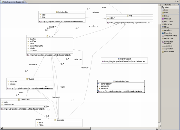
Figure 1. Screenshot showing an example of an editor using GMF.
GMF components
The name of GMF can be easily divided into two parts: the first one refers to graphical operations, the second - modeling. EMF (Eclipse Modeling Framework) is the most often used for modeling in Eclipse and that is why this technology is the base of GMF. On the other hand GEF (Graphical Editing Framework) is used to do graphical operations in Eclipse and is the base for building a visual editor in GMF. Despite the fact that GMF depends on EMF and GEF, only little knowledge of these two is required to start working with GMF. Only when creating advanced editors you have to know EMF and GEF better. In this article we will focus on GMF components (if it is possible), leaving out the details of the other technologies on which GMF depends.
How does it work - a bit of theory
Before moving to a concrete example it would be good to get to know with components of GMF - a diagram with dependencies of the components is shown on figure 2.
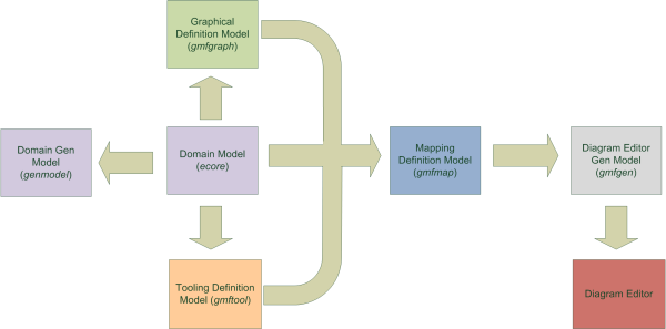
Figure 2. A diagram with dependencies of GMF components.
To start working a model is needed on which we will operate. Model has to be defined in the form of an ecore file, which is later used to create other elements. If creating this file directly is too difficult we can use an editor from GMF which allows us to create a model in a visual way (a screenshot of this editor is shown on figure 2). To use this feature right click on the select ecore file in the Package Explorer view and choose Initialize ecore_diagram diagram file from the menu - it will generate a file with an ecore_diagram extension, which we could edit in a visual way (and the changes will be propagated to the right ecore file). When our model is ready we need a genmodel file from which we will generate the code of our model and edit project. At this point our work with the model is done and we start working with standard GMF elements. We generate gmfgraph file from the ecore file - it will contain the definitions of graphical elements which will appear in our editor. To put the defined elements in the editor we need appropriate tools available on the editor palette - we define them in a gmftool file, which also is generated from the ecore file. After that we have to connect all these elements together - this is done in a gmfmap file (in this file we define e.g. which model element is to be created with the selected tool and what graphical element should represent it). Next a gmfgen file is generated from gmfmap in which we can set some properties of the editor. When the gmfgen file is ready we can generate editor's code as an Eclipse plugin.
Creating an editor
After a theoretical introduction it is time to try creating an editor using GMF. To use GMF it has to be installed in Eclipse. As GMF is a part of Eclipse Ganymede, we can easily download it using P2. Select Help -> Software updates... from the main menu. Open the Available Software in the window tab and expand the Ganymede Update Site node, check the Models and Model Development category and select Graphical Modeling Framework SDK. Click the Install... button in the upper right window corner and after a little while we will be asked for confirmation, click Next, on the next page accept the license (I accept the terms of the license agreement) and click Finish. Eclipse will ask to restart the environment, click Yes and GMF should be a part of our IDE. We can start working after successfully installing GMF. Let us start with creating a new project by selecting File -> New -> Project from the main menu and choosing New GMF Project from the list of available projects. Give a name of the project in the wizard (gmf.example in this article) and click Finish. The main component of GMF is the model stored in the ecore file, that is why the first step to create an editor is to define a model, which we would like to edit. Our model will be quite simple for the sake of learning, not to complicate things. Our model is shown on listing 1 as an ecore file. In order to use it, create a new file with the ecore extension under the model directory (company.ecore). We should see an error message that the file is invalid, but do not worry about this fact. Open the file in text mode (in the Package Explorer view from the context menu select Open With -> Text Editor).
    <?xml version="1.0" encoding="UTF-8"?>
    <ecore:EPackage xmi:version="2.0"
        xmlns:xmi="http://www.omg.org/XMI"
        xmlns:xsi="http://www.w3.org/2001/XMLSchema-instance"
        xmlns:ecore="http://www.eclipse.org/emf/2002/Ecore"
        name="company"
        nsURI="gmf.example"
        nsPrefix="gmf.example">
      <eClassifiers xsi:type="ecore:EClass" name="Company">
        <eStructuralFeatures xsi:type="ecore:EAttribute"
            name="companyName"
            eType="ecore:EDataType http://www.eclipse.org/emf/2002/Ecore#//EString"/>
        <eStructuralFeatures xsi:type="ecore:EReference"
            name="employees"
            upperBound="-1"
            eType="#//Employee" containment="true"/>
        <eStructuralFeatures xsi:type="ecore:EReference"
            name="ownedComputers" upperBound="-1"
            eType="#//Computer" containment="true"/>
      </eClassifiers>
      <eClassifiers xsi:type="ecore:EClass" name="Manager"
          eSuperTypes="#//Employee">
        <eStructuralFeatures xsi:type="ecore:EReference"
            name="managedDevelopers" upperBound="-1"
            eType="#//Developer"/>
      </eClassifiers>
      <eClassifiers xsi:type="ecore:EClass" name="Employee">
        <eStructuralFeatures xsi:type="ecore:EAttribute" name="name"
            eType="ecore:EDataType http://www.eclipse.org/emf/2002/Ecore#//EString"/>
        <eStructuralFeatures xsi:type="ecore:EReference"
            name="usedComputers" eType="#//Computer"/>
      </eClassifiers>
      <eClassifiers xsi:type="ecore:EClass" name="Computer">
        <eStructuralFeatures xsi:type="ecore:EAttribute" name="name"
            eType="ecore:EDataType http://www.eclipse.org/emf/2002/Ecore#//EString"/>
      </eClassifiers>
      <eClassifiers xsi:type="ecore:EClass" name="Developer"
          eSuperTypes="#//Employee"/>
    </ecore:EPackage>
Type or paste the contents of the listing into the opened editor, save the file and model is ready as an ecore file (it is worth opening the ecore file in the Sample Ecore Model Editor). It would be good to know the model, because it will be needed later in the article. To continue the work we will need a model as Java code and an edit project (which allows us to easily operate the model). That is why we will generate a genmodel file from the ecore file - EMF Model wizard available under File -> New -> Other -> Eclipse Modeling Framework -> EMF Model. Give a name of the file (company.genmodel) and select that it should be created in the model directory of our project. By clicking Next we move to the page on which we select the type of our model (in our case Ecore model). On the next page give the path to the model file - it is best to click Browse Workspace and select the company.ecore file. Click Next and Finish - company.genmodel file should appear in the model directory. Open the file created by the wizard and right clicking the top element select the options: Generate Model Code and Generate Edit Code. Now it is time to leave out EMF and use GMF exclusively.
Let us start with the visual side of our editor. Right click on the ecore file and select New -> Other -> Simple Graphical Definition Model from the context menu (Graphical Modeling Framework category). Give the name - e.g. company.gmfgraph - in the wizard (it is best to put the file in the model directory so all elements of our editor would be in one place) and click Next. On the next page select the element which will be a container for all the elements - in our case Company and click Next. After that select the elements from the model which are to be shown. At this time we want to create Manager and Employee objects as well as links between them and their names (the result of this is shown on figure 3). After selecting the needed options we close the wizard by clicking Finish.
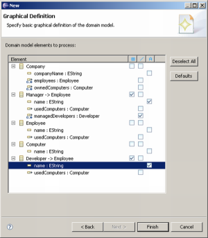
Figure 3. A page of the graphical definition wizard showing which model elements will be shown.
It is easy to notice a new file in the model directory, with a gmfgraph extension. It would be good to take a look at its contents, because all changes regarding the graphical elements of our editor will be done there.
The next step is defining the tools which will be available on the editor's palette. In order to do this, right click on the ecore file and select New -> Other... -> Simple Tooling Definition Model (Graphical Modeling Framework category). Give the name of the file - e.g. company.gmftool (it is best to put the file in the model directory as before) and click Next. Again choose what is the container for our editor (Company) and move to the next page. The last step of the wizard allows us to define which model elements should have tools created on the palette. We want to add Manager, Employee elements and links between them, so the result should look like figure 4. Click Finish to close the wizard.
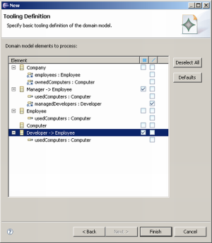
Figure 4. A page of the tool definition wizard showing for which model elements tools will be created.
Having the model, graphical elements definitions and tools, we have to connect them all together. Right click on the ecore file and select New -> Other -> Guide Mapping Model Creation (Graphical Modeling Framework category). As with the other wizards, give the name of the file storing the mapping definitions - e.g. company.gmfmap (again it is best to save it in the model folder). On the second page select the container (Company) and click Next. After that select the tools definition; click the Browse Workspace... button, choose the gmftool file and click Next. The last page is the most important one, because it allows us to define which elements will be the nodes in our editor and which will be links. Remove Computer (Manager; ownedComputers) from the Nodes section and usedComputers : Computer (ManagerManagedDevelopers; <unspecified> from the Links section; the page should look like on figure 5. Click Finish to close the wizard.
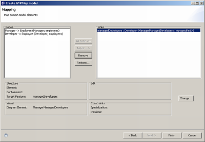
Figure 5. A page of the wizard showing nodes, links and attributes.
We have to look into the generated gmfmap file and check (in the Properties view) whether Diagram Label attribute is set for the Feature Label Mapping elements. If they are not set (the wizard does not always guess are intentions) we will have to enter the following values for them:
- Diagram Label DeveloperName for the element of that type under the Node Mapping <Developer/Developer> node
- Diagram Label ManagerName for the element under the Node Mapping <Manager/Manager>
We can check if the right tools match the right elements:
- Node Mapping <Developer/Developer> node should have the attribute Tool set to Tool Developer
- Node Mapping <Manager/Manager> node should have the attribute Tool set to Tool Manager
- Link Mapping node should have the attribute Tool set to Tool ManagerManagedDevelopers
The mapping is ready, we only have to generate the generator model. Right click on the gmfmap file and select Create generator model... Give the name of the file - e.g. company.gmfgen (again select model as the destination folder), click Next until the last page and close the wizard clicking Finish.
Now we can generate the code of our editor. Right click the gmfgen file and select Generate Diagram Code. A new project should appear in our workspace. It contains the code of the editor as a plugin. In order to test our editor we have to run Eclipse with that plugin (as well as with the plugin containing our model and edit plugin). Click Run -> Run Configurations from the main menu, select Eclipse Application from the list on the left side and click New launch configuration. A new configuration is created which allows us to run a new instance of Eclipse with selected plugins (we will not get detailed about it here). Type in the name of our configuration and check if our plugins are selected on the Plug-ins tab. Apply the changes and run our new configuration. Create a new project in the new Eclipse instance, right click on the project and select New -> Other -> Company Diagram (we can change that name). Give the name of the file and click Finish. Our editor should open in which we could add new elements from the palette on the right side (figure 6).

Figure 6. A screenshot of the editor right after generating it.
Adding new elements
We managed to create a fully functional editor in a short time without writing a single line of code. Instead we created and edited a few XML files (using wizards and editors simplifying this task). Now it is time to do something without wizards - let us add the capability to create new Computer elements (again we will not write any code).
Let us think for a moment - where will we make changes? First, we have to define new graphical elements (gmfgraph file modification). Second, we have to add new tools to the palette (gmftool file modification). Third, we have to map model elements to the graphical elements and show which tool will be used to create those elements (gmfmap file modification). Knowing that we can start working. Let us start new graphical elements. After opening the gmfgraph file we will see that the main element is Canvas. Its contents are:
- shapes available in the application (Figure Gallery Default node)
- nodes - graphical representation of model elements
- diagram labels - nodes labels
- connections - lines showing relations between model elements.
Let us assume that we want Computer elements be displayed as ellipses. Let us define their appearance first: begin with creating a figure descriptor which will contain all information about our new figure. In order to do this right click on the Figure Gallery Default and select New Child -> Figure Descriptor. A new node will be created which we will name in the Properties view (e.g. ComputerFigureDescriptor). Now we have to define our figure appearance (even many base figures). Right click on the newly created descriptor and select New Child -> Ellipse. Give the new node a name e.g. ComputerEllipse and change other properties if you like. We would like that the figure had a label, so right click on the ComputerEllipse and select New Child -> Label. Let us name it ComputerNameLabel. We have to create an access rule to the label in order to refer the label later (we will see the usage for that) - right click on the ComputerFigureDescriptor and select New Child -> Child Access. Select the element which we would like to have the access to in the properties - in our case the Figure property set to ComputerNameLabel. The appearance of the figure is defined, now we have to create a node definition for it. Right click on the Canvas and select New Child -> Nodes Node. Give a name for the new node (e.g. ComputerFigure) and connect it with our figure by giving the name of the figure descriptor (ComputerFigureDescriptor) as the Figure property. Create a diagram label node for the created label, so the editor would be "aware" that we want to display it. Right click Canvas and select New Child -> Labels Diagram Label. Give it a name (e.g. ComputerName) and connect it with a figure descriptor like previously. The access rule is useful now - set the Accessor property to Child Access getFigureComputerNameLabel.
The graphical definition is ready, we can define the tools which we would like to add (in our case we would like to add Computer elements, so we need one new tool on the palette). Open the gmftool file, right click on the Tool Group node and select New Child -> Creation Tool from the menu. Give a name for the new node (Title attribute), e.g. ComputerTool and a description. We have to define icons for our element which will appear on the palette and in the editor - default (in our case) or selected by us. In order to add default icons right click the newly created node and select New Child -> Large Icon Default Image as well as New Child -> Small Icon Default Image. That is the end of gmftool file modifications.
The last piece of work to do is to connect the model, the graphical definition and tools which means modifying the gmfmap file. After opening it we will see that the main node is called Mapping and stores all defined mappings. We will add a Top Node Reference mapping because it concerns the top node of the editor. Right click Mapping and select New Child -> Top Node Reference. In this new node we have to set where to store the element represented by the node (Containment Feature attribute). In our case it will be ownedComputer. After that right click the new node and select New Child -> Node Mapping and there we set the mapping details: Element attribute - element from the model (Computer), Diagram Node attribute - node name from the graphical definition (ComputerFigure), Tool attribute - tool name defined in the gmftool file (ComputerTool). We would also like to display Computer name as a label, so we right click on the node and select New Child -> Feature Label Mapping. We have to set the Features attribute to name for the new node (because this Computer attirbute we would like to display) and Diagram Label property should point to the diagram label defined in the gmfgraph file (ComputerName).
That is the end of our work. Now it is time to regenerate gmfgen file, editor code based on that and check whether our editor works as we expected. The result of our work is shown on figure 7.
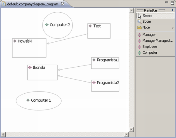
Figure 7. A screenshot showing the editor after changes.
Summary
Basic capabilities of the GMF project were presented in this article as well as how easily and quick one can create a fully functional graphical data model editor. GMF features are of course broader, that is why I encourage to get familiar with samples and tutorial available on the internet and experiment with the technology.
Internet
GMF home page: http://www.eclipse.org/gmf/
GMF tutorial: http://wiki.eclipse.org/index.php/GMF_Tutorial
GMF FAQ: http://wiki.eclipse.org/Graphical_Modeling_Framework_FAQ
GMF in 15 minutes: http://www-128.ibm.com/developerworks/opensource/library/os-ecl-gmf/
Article about an additional GMF view: http://eclipser-blog.blogspot.com/2007/06/gmf-project-in-5-minutes-with-gmf.html
A collection of posts about EMF: http://eclipse-po-polsku.blogspot.com/search/label/EMF (in polish)
Translation: Paweł Cegła


Nobody has commented it yet.